


General Technical Information
|
Our ceramic capacitors are composed of conducting plates (electrodes) separated by an insulating material (dielectric) that is polarizable. They are manufactured in a wide variety of sizes and shapes determined by use requirements. Barium Titanate has excellent Ferro electric properties and is the basic material used by WCI in the manufacture of dielectrics. Basically, increasing the amount of Barium Titanate in the composition will result in a higher dielectric constant. The practical formula for determining capacitance is: 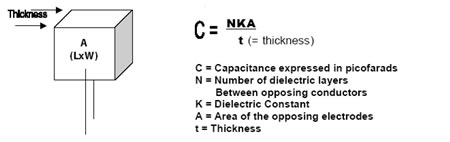 Types of Ceramic Microwave SS High Voltage SL
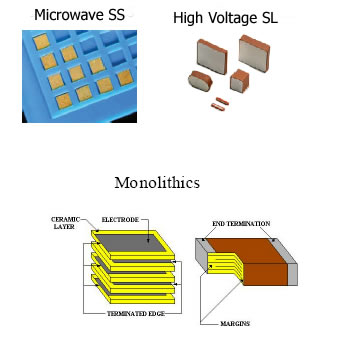 SINGLE LAYER-A single layer ceramic capacitor is formed by a dielectric block with an opposing electrode on each side. The ceramic has a higher dielectric constant than thick film and a reasonable capacitance can be achieved since glass is not required for bonding. This type is primarily used in Monolithics high voltage or high frequency applications. MONOLITHIC - A multilayer ceramic capacitor is formed by the parallel assembly of single layer ceramic capacitors. The unique manufacturing process hermetically seals the opposed electrodes inside the dielectric so thinner dielectrics can be used to increase the capacitance per unit volume. Due to the high volumetric efficiency achieved, they are ideal for applications where higher capacitance than single layers are required. These descriptions of the types of the types of ceramic capacitors, treat a complex subject in an elementary fashion. To avoid misapplication, further information should be obtained from WCI. Classes of Ceramic Dielectrics Ceramic dielectric materials fall into three classes as defined by industry/military standards. These materials are manufactured to perform within specified limits. WCI has proprietary formulations with particular emphasis placed upon high voltage performance designed to meet and exceed specified requirements. CLASS I NPO/N2200 These materials have extremely stable characteristics over varied temperature, voltage and frequency ranges; however, the low percentage of barium titanate restricts dielectric constants (K) to a range of 10-100. Being non-ferro electric they show little aging or voltage coefficient. Modification of these materials can result in temperature compensating dielectrics with constants in a range of 100-300. This will also increase the temperature effect of capacitance change from 30 ppm/°C to the 1000-3300 ppm/°C. CLASS II BR/BZ This class of mid-K dielectrics has a broader tolerance over temperature, voltage, and frequency than does NPO; however the dielectric constants fall in a much higher range of 1000-2500. Selection of the dielectric used for any given application to achieve the capacitance required at any given temperature, voltage, or frequency is critical. CLASS III Z5U/Y5V This class represents the highest dielectric constants with a range of 3500-12,500. The temperature, voltage, and frequency are effected very severely by a deviation from 25°C and 1 Vrms. Increased capacitance can generally be achieved by proper selection of a lower class dielectric if higher temperatures or voltages are to be used. Voltage Effects 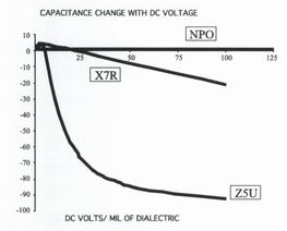 All ceramic capacitor values are stated at a rating of 25°C and 1Vrms. The application of voltage to a capacitor causes a change in the capacitance and volume efficiency as illustrated to the right. Another important consideration in capacitor design is the break down or failure voltage of a capacitor body. This phenomenon takes place when the applied voltage causes permanent failure through a given thickness of ceramic. The dielectric strength of all insulating materials varies inversely with the square root of the thickness. The probability of a flaw increases as the thickness of a fixed area increases. Flaw rates will vary depending upon the process and the raw material selection. 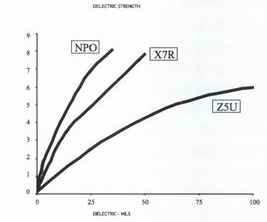 Dielectric strength versus thickness is shown in the Figure to the left and illustrates that making a part thicker to increase the voltage rating does not necessarily obtain the desired result in total. The flash voltage or over-rated test voltage has a limiting effect on how much capacitance can be achieved in a given area. The dielectric strength is not directly proportional to thickness and voltage strength falls off quite rapidly at greater thicknesses. Having a flash test requirement of 2X could require the dielectric thickness to be increased to 4X to insure the same degree of reliability. For these reasons, flash voltages of 1.5X for 500V to 1KVDC and 1.2X for higher voltages have been set as industry standards and have proven by experience to be the best balance between reliability and volumetric efficiency. Surge Current High surge currents can have damaging effects on ceramic capacitors and electrodes. Barium Titanate can be ferroelectric or piezoelectric, depending on how it is doped. The higher "K" dielectrics appear to retain a slight peizoelectric tendency; therefore a high current surge could cause mechanical damage to a capacitor. This could show as cracking thereby creating a short circuit failure, or the burn-out of internal electrodes; thus causing a permanent reduction in capacitance. By controlling the design parameters and utilizing low ESR precious metal electrode systems, surge currents greater than 10 amps are obtainable without sacrificing quality and reliability. Energy Density The amount of energy stored in a capacitor is defined as ½CV². The energy density, or joules/in³, coupled with shape and dielectric material considerations are important factors in designing a capacitor. It is practical for high capacitance and high voltage to achieve energy densities of 6 to 10 joules/in³. WCI has extensive experience with high capacitance at high voltage and employs original designs to avoid piezoelectric effects and other potential problem areas. Corona Corona is the ionization of a gas by applied voltage. The ions are accelerated by voltage stress and discharge their energy upon impact with a solid. Effects of corona are dependent on the frequency of generation and energy dissipated on impact. Corona inception occurs when voltage is applied across a void or other imperfection in the structure of the ceramic dielectric. Ceramics are made of hard materials with high melting points and would require extended exposure to corona to sustain critical damage. Capacitor Mounting After acquiring a high quality ceramic capacitor it is extremely important that it is installed in your circuit without damage. The two most common methods of affixing are conductive epoxy and soldering. Conductive epoxy is popular due to the ease of application. This type of adhesive contains metal particles for electrical contact and a degree of mechanical strength; however it is of lesser strength than solder and the D.F. can increase due to lower conductivity. This attachment technique is only good in circuits not exposed to atmosphere. Solders come in many melting point compositions and must be applied very carefully. If capacitor chips are being used, the chip should be cautiously preheated to just below the liquidous temperature of the solder and then the solder should be applied quickly to avoid thermal shock or leaching of the termination. Leaded devices are not as sensitive, but care must still be taken to prevent thermal shock and reflow of solder onto the capacitor. Chips larger than 2725 or thicker than .100" are not recommended for solder mounting, particularly on epoxy boards. They can be used with some success on hybrid boards with carefully controlled preheating. Conductive epoxy or the use of leaded components are recommended for any solder attachment of these large devices. Gold, silver, palladium-silver, or nickel barrier terminations are available. Consult the factory. WCI's technical service group is available to help with any mounting problems you may encounter. Temperature Effect Class II and III dielectrics contain substantial amounts of the ferroelectric material Barium Titanate. Barium Titanate undergoes a crystalline change at approximately 125°C. This is called the curie point. After this transition occurs the ability to become polarized is drastically reduced and the "K" is diminished as shown at right. The X7R dielectrics are blended to broaden this precipitous change in "K", resulting in a more moderate performance as shown. The Z5U dielectrics, with the highest percentage of Barium Titanate, are formulated to shift this curie point closer to room temperature. This takes maximum advantage of Barium Titanate's high "K" and results in the most extreme performance./
Aging An effect that is sometimes overlooked by capacitor users is aging. When the capacitor passes through the curie point of 125°C, a crystalline change occurs. As the capacitor cools to room temperature, the capacitance returns to its original 25°C value. The rate of capacitance decrease or "aging" varies with "K" and generally increases with higher dielectric constants. This rate of change is expressed in percent change per decade hour. For NPO the rate of change is zero; with X7R's varying between 0.5% to 2% per decade hour; and Z5U's varying as high as 4% to%5 per decade hour. As all ceramic capacitors go through temperature processing, it is important to understand how this could affect the value of a capacitor that has been sitting on a shelf for many decade hours. (General industry practice uses 1000 hours as the reference time for tolerance determination.) Contact Wright Capacitors, Inc. for Pricing and Production information |